This is one of many audio level indicator circuit. The different is that this circuit
should be connected tho the output of amplifier while the other
indicators connected before amplifier module. This circuit will show the
real audio output by LED indicator level.
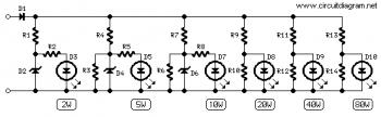

R1_____________220R  1/2W Resistor
R2,R5,R6,R8____100R  1/4W Resistors
R10,R12,R14____100R  1/4W Resistors
R3_____________220R  1/4W Resistor
R4,R7__________330R  1/2W Resistors
R9_____________560R  1/2W Resistor
R11____________820R  1/2W Resistor
R13______________1K2 1/2W Resistor

D1___________1N4004  400V 1A Diode
D2,D4,D6__BZX79C2V7  2.7V 500mW Zener Diodes
D3,D5,D7,D8,D9,D10   Red LEDs (Any dimension and shape) (See Notes)
Notes:
- The output power indicated by each LED must be doubled when 4 Ohms loads are driven.
- The circuit can be adapted to suit less powerful amplifiers by reducing the number of LEDs and related voltage dividers.
- LEDs of any dimension can be used, but rectangular shaped devices will be more suitable to be compacted in bars or columns.
- For a stereo amplifier, two identical circuits are required.
No comments:
Post a Comment